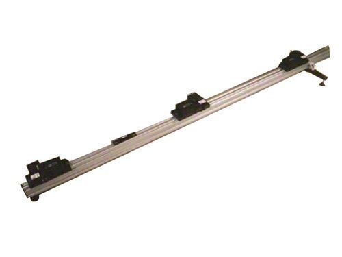
ART Laser String II Four Wheel Alignment

ART Laser String II Four Wheel Alignment
The "Laser String II" is a triple laser head tool using laser line generation technology developed by A.R.T. for CART technical inspection. Laser String II ( Triple )is the first 3D laser measurement device of its kind for performing four wheel alignments, chassis inspection, and chassis construction using the vehicle centerline as reference. Laser String II simulates traditional three string alignment method used by racers but adds a third dimension in the vertical axis. It also has a much greater potential for other uses beyond suspension alignment. The Laser String is currently used by over 75% of the NASCAR teams and considered the corporate standard for many of the top championship teams. Not only is the Laser String the standard gauge for chassis setup, it is also considered one of the key components in stock car frame construction and body panel placement.
Laser String II is a custom built three head laser system for projecting three vertical parallel reference lines. The center laser beam is used to establish or target the vehicle centerline. The five head lasers uses three lasers for establishing vehicle center line. The two outer laser beams, on each side of the race car, are calibrated to the center laser beam. Using the triple is very simple. Place the gauge on the ground, level the high precision bubble level, align the center laser to your vehicle centerline, and your ready to go.
Each laser head has three axis adjustment capabilities for calibration or custom setup. The first adjustment is for "X" axis. This is performed by simply sliding the laser head from side to side on the supplied aluminum rail to set the spacing between the laser beams. The new linear bearing allows the head to move from side to side without distortion. The second adjustment allows the laser beam to "pan" horizontally for setting the laser beams parallel to each other. The third adjustment is used to tilt the laser beams so that they are vertical and plumb to each other. The standard tilt angle range is +/- 4 degrees and can be adjusted within this range for special applications. Steeper angles are available on request. Both tilt and pan adjustments have a fine 80 pitch resolution. Individual laser heads are available for special applications that require custom fixtures. We have sold many for chassis construction and body panel alignment.
The single and dual heads are sold to customers who have special applications and require custom fixturing for inspection, chassis alignments and chassis construction.
How to Setup
The center laser is aligned to reference points representing the vehicle centerline in the chassis. These points must be created by the customer but the Laser String II can help find them. These reference points are in most cases the center point between suspension pivot points on the front and rear suspension. To get an understanding we will use a vehicle that has four wheel double arm independent suspension. The inner mounts where the "A" arms connect to the chassis will be our reference points. Many people refer to them as "hard points". The center points between the two front "A" arm hard points and the center between the two rear "A" arm hard points represent the vehicle centerline. Using the center laser of the laser string II simply align the laser to these two points, thus createing a vehicle centerline. The two outer lasers, one on each side of the vehicle, are now parallel to the vehicle center line. Your measurements would then be taken from these three laser for any type of chassis measurement and wheel alignments.
The Triple Laser String eliminates strings and the very time consuming setup. All you have to do is align the center laser beam of the triple to your front and rear reference points and you are finished. Your measurements would then be taken from these two outer laser beams. A center target point between the chassis hard points must be created before the laser can be used, but the laser can help you do this. This will only need to be performed once on your vehicle and should last the entire life of the vehicle. Assuming your triple is calibrated and leveled, aim the center laser under the vehicle at the approximate centerline. The laser beam will create a red line and scribe the under carriage of the vehicle. Shooting the laser from the rear of the vehicle is recommended but not required. Stretch a tape measure between the two front hard points and another between the two rear hard points and center the laser on both tape measures. With the laser on the centerline, mark the chassis permanently in such a manner that you can easily align the laser to these marks whenever you need to align your vehicle.
If your chassis is of such a design where a permanent mark cannot be made between the hard points for the laser to be aligned, the laser can help you. With the laser still aligned to your vehicle centerline, establish a higher point of the chassis that you can easily access. Drop a plumb line from this point and align the plumb line to the laser beam. Once it is aligned, mark this point permanently, so that you can easily go back to it with your plumb line. Another method created by Porsche, of which the triple was originally designed for, was to drill and tap a hole at this reference point so you could use a long threaded stud that could be easily attached and become your target. The hole could also be used for attaching a plumb line.
Note: By using plumb lines made of poly fishing line the line will glow when the laser beam hits it. To aid in accurately aligning the laser beam to the plumb line, hold a piece of paper close behind the string, without touching the string. You will able to see if the laser beam is centered on the string. Another alternative is to create a target with a flat surface 3/8 of an inch wide and attaching three 1/8" wide strips of retro reflective tape to it. Two strips would be placed vertically parallel to each other with a space between them equal to the laser beam width. The third strip would be placed above the two strips but on the centerline. This arrangement works very well for long range accurate targeting.
Having made your reference marks or targets, set the triple on the ground, level the bubble level and simply align your center laser to the targets. Since the two out lasers are calibrated to the center laser, you will now have a three line 3D parallelogram to perform all wheel alignments. As a last note, use common sense and you will find dozens of uses for the Triple Laser String II.


